Measuring the depths

Steam power and sounding machines

NMS T 1999 382 2 PF1076667

Wind and steam power, combined with human labour, ingenuity, and the materials of the ship, propelled Challenger on its voyage around the world while specialised instruments surveyed the ocean’s depths.

Challenger moved under steam and sail power, fusing new and old maritime technologies. Steam power had many advantages but consumed large amounts of coal, a bulky, solid fuel. For this reason, the crew operated the ship under sail when travelling long distances across the open oceans. Steam power was reserved for carrying out deep-sea investigations to keep the ship stationery against wind and currents and to power winches to bring material up from the ocean floor.

Challenger carried out observations at 362 deep sea stations during its circumnavigation. At each station, the crew determined the exact depth of the ocean floor and direction and rate of the current; collected samples of seawater, sediment and marine life; measured temperatures at different depths; and observed and noted atmospheric and other meteorological conditions.

The Hydrographic Office of the Admiralty was responsible for sourcing the specialised instruments the crew used at these stations, working closely with manufacturers on experimental designs.

One of the great difficulties of 19-century ocean science was that the deep sea could not be directly observed. Knowledge of the ocean depended on the movement of instruments to and from the ship, floating at the ocean surface, and the ocean depths below.

Deep-sea sounding is one of Challenger’s greatest contributions to oceanography. A process of measuring the depth of a body of water, sounding was carried out at each of the 362 stations, making visible the great depths, broad plains, and mountain ranges of the Atlantic Ocean, Pacific Ocean, and the Southern Ocean basins.

To collect ooze, mud, rock, and sand from the sea bottom to the surface required a modification of existing sounders which were primarily used to determine the depth of water beneath the ship’s hull. In 1868, HMS Hydra sounded across the Arabian Gulf in preparation for laying the Indian Cable. During this voyage a blacksmith and two sailors aboard the Hydra invented a sounder.

The Hydra, illustrated here, had a hollow brass tube (A) and a butterfly valve at its bottom (B). When it hit the bottom, the weight of the sounder drove the end of the cylinder into the ground; a spring (D) then released the weights (F). When the sounder was hauled up without its sinkers, the butterfly valves closed and trapped a sample of the seabed.

This Hydra sounder in the collection of National Museums Scotland may have been one of the six used in the expedition when it first set out in 1872. During the first leg, between Portsmouth and Cape Verde, they were the primary instruments used for deep-sea sounding.

Unfortunately, these instruments could only collect small samples of the seabed and were difficult to operate. The spring had to be delicately adjusted to release the sounder’s weights at the correct moment when striking the bottom of the ocean. A sudden change of tension on the line could prematurely release the weights before it reached the seabed.

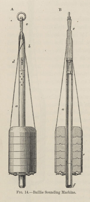
The Baillie was invented on HMS Sylvia in 1871 by Navigating Lieutenant Charles William Baillie (1844-1899), addressing some of the shortcomings of the Hydra. In 1872, after Sylvia was decommissioned, Baillie sent a model and design of his new sounder to the Hydrographic Office. There, the improved sounder could be built and replicated, and then sent to survey ships for testing and use.

The Baillie replaced the Hydra’s complicated spring with a freely moving iron bar, indicated as (c) in this illustration. When the Baillie sounder was held upright by the sounding line, the wire that held the sounding weights rested on two metal ‘shoulders’ or small hooks. When the sounding tube hit the bottom, the sounding line slackened and the ‘shoulders’ retracted inside the sounding tube and the weights were released.

Baillie sounders like this one from the collection of National Museums Scotland were deployed on Challenger in late August 1873 as the primary instrument for conducting deep-sea soundings throughout the southern Atlantic, an extensive tour of the Pacific, and part of the Southern Ocean.

Most notably the Baillie was instrumental in the discovery of the Challenger Deep—now known as the Mariana Trench—the deepest point on the surface of the Earth. To measure this great depth, the sounder, consisting of a 450lb lead weight attached to a line, was deployed on 23 March 1875 to the ocean bottom and was retrieved from a depth of 4,475 fathoms (or seven miles).

The Baillie was used with a hemp sounding line, a material that had been tried and tested and on which key measurements and other instruments could be attached including a collecting water bottle, pressure gauge and thermometers. In addition to the measurement of depth, temperature measuring was one of the chief objectives of the expedition and used to formulate theories about the global circulation of the oceans and the distribution of marine life.

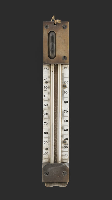
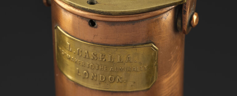
Casella-Miller thermometers, like these below from National Museums Scotland, were used extensively on Challenger. Their U-shaped mercury tube recorded maximum and minimum temperature as the thermometer was lowered and raised into the ocean.

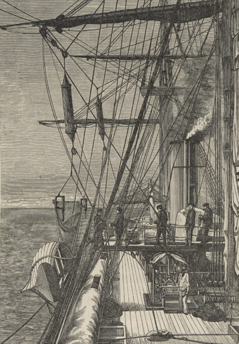
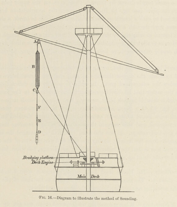
Sounding on a large warship like Challenger was more complicated than on smaller survey vessels so further modifications to the ship and this process had to be made. The ship’s height above the water made it necessary to carry out sounding from a raised platform above the main deck, with the line attached to the main yardarm which held the sails. After touching the bottom, the sounder was hauled to the surface with the help of a small steam engine.

The ocean depths put strain on both the yardarm and the sounding line. The hemp sounding line had a breaking strain of 700kg, enough to support the sounder and its weights, but the motion of the ship and the movement of the ocean added additional tension. Forty accumulators consisting of rubber bands, shown as (B) in this diagram, were added to the line to absorb an increase in pressure and prevent the line from breaking.